
This technical guide explains how single plate wafer check valve works with detailed component anatomy, wafer check valve working principle diagrams, step-by-step forward flow and backflow prevention cycles, spring-loaded disc dynamics, cracking pressure analysis, disc flutter causes and prevention, comparison with dual plate, swing, and lift check valve mechanisms, installation orientation effects on operation, pressure drop and flow characteristics, common failure modes, API 598 testing procedures that verify correct valve operation, and Mill Test Report (MTC 3.1 per EN 10204) documentation requirements. This guide is written for mechanical engineers, piping designers, maintenance technicians, and procurement professionals who work with SS304 and SS316 wafer check valves in industrial piping systems across chemical, pharmaceutical, food, water treatment, HVAC, and process industries in India.
KELOR Valves, Ahmedabad – trusted KELOR valve supplier India – supplies single plate wafer check valves from verified and quality-assured vendor partners. All valves undergo factory hydrostatic shell testing and seat leakage testing per API 598 before dispatch. MTC 3.1, API 598 test certificates, and hydrostatic test reports are provided with every order to ensure full quality traceability.
⚡ Quick Reference
Get Fast Quotation — SS304 / SS316 Wafer Check Valve
WhatsApp size list, quantity, seat material, and pressure class — receive competitive project pricing within 2 hours from KELOR valve supplier India.
Get Price on WhatsApp 📩 Get Price by Email1. What Is a Single Plate Wafer Check Valve?
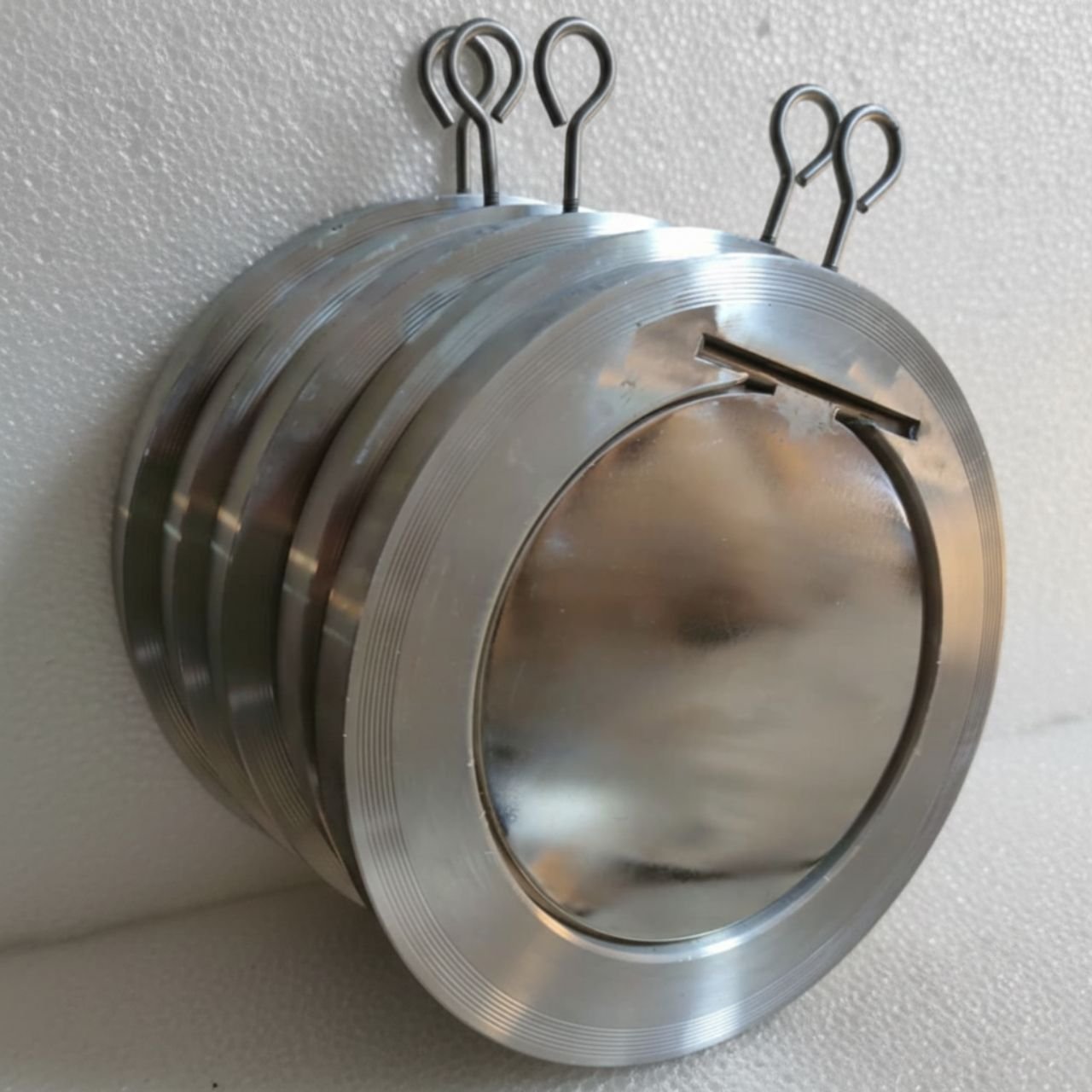
A single plate wafer check valve (also called a single disc wafer check valve or single plate NRV) is an automatic, non-return valve designed to allow fluid flow in one direction only while preventing reverse flow. Understanding how single plate wafer check valve works is essential for proper valve selection. It belongs to the wafer-style check valve family defined under API 594, which means the valve has no flanged ends of its own and is installed by sandwiching it between two adjacent pipe flanges using stud bolts and nuts. The compact wafer design makes it the lightest and most space-efficient check valve format available for industrial piping systems.
The wafer check valve working principle uses exactly one flat or slightly conical disc as the closing element. This disc is mounted on a hinge pin that runs through the valve body and pivots on a single axis. A torsion spring is mounted around the hinge pin to provide the closing force that returns the disc to the sealed position when forward flow ceases or reverses.
2. Internal Components and Anatomy
Understanding each internal component is essential to understanding how single plate wafer check valve works as a complete system. The single plate wafer check valve contains six primary components that work together to achieve automatic non-return operation.
2.1 Component Specifications
| Component | Material (SS304) | Function in Valve Operation |
|---|---|---|
| Valve Body | SS304 (ASTM A351 CF8) | Pressure-containing envelope that houses all internal components and provides mounting points for the hinge pin and seat ring. |
| Disc (Single Plate) | SS304 / SS316 | The moving closure element that swings open with forward flow and closes against the seat to prevent reverse flow. |
| Hinge Pin | SS304 / SS316 | Central pivot axis passing through the body wall on which the disc rotates with minimal friction. |
| Torsion Spring | SS302 / Inconel | Provides the closing force that returns the disc to the sealed position. Spring constant determines cracking pressure and closing speed. |
| Seat Ring | EPDM / NBR / FKM / PTFE | The sealing surface against which the disc closes. Soft seats provide zero-leakage sealing at low pressures. |
| Gasket Faces | Full-face gasket | The sealing surfaces on both sides of the wafer body that mate with the pipe flange gaskets. |
3. Forward Flow Opening Mechanism
The opening of a single plate wafer check valve is a purely mechanical process driven by the differential pressure across the disc and the kinetic energy of the flowing fluid. No external power source or control signal is needed.
3.1 Step-by-Step Opening Sequence
Rest Position (Closed)
With no flow, the torsion spring holds the disc firmly against the seat ring. The valve is fully sealed.
Pressure Build-Up
Forward pressure begins building on the upstream side, creating a force vector that pushes the disc away from the seat.
Cracking (Initial Opening)
When forward pressure exceeds the spring closing force, the disc begins to separate from the seat (cracking pressure: 0.3 to 0.7 psi).
Disc Swing (Full Opening)
As flow velocity increases, the disc swings upward around the hinge pin to approximately 65 to 70 degrees, offering minimal flow resistance.
4. Backflow Prevention and Closing Mechanism
The closing mechanism relies on the combined action of the torsion spring and the differential pressure across the disc. The spring-loaded design provides one of the fastest closing responses among all check valve types, typically completing the full closing cycle in less than 0.1 seconds.
4.1 Step-by-Step Closing Sequence
Flow Velocity Decreases
When the pump slows down, forward flow velocity drops, reducing the hydrodynamic force on the disc.
Spring Force Dominates
When hydrodynamic force drops below spring torque, the spring begins pulling the disc back toward the closed position.
Rapid Disc Swing
The spring accelerates the disc rapidly toward the seat. Closing speed increases in the final degrees of travel.
Seat Contact
The disc contacts the seat ring and the spring provides the final sealing force, absorbing impact energy.
Full Seal Achieved
The disc is fully seated with the spring maintaining sealing pressure. Zero leakage is achieved for soft-seated valves.
Backflow Blocked
If reverse pressure develops downstream, it presses the disc more firmly against the seat, improving the seal.
5. Role of the Spring in Valve Operation
The torsion spring directly controls three key operational parameters: the cracking pressure, the closing speed, and the sealing force when the valve is closed. Selecting the correct spring rating for the application is essential for reliable valve operation.
💡 Spring Selection Tip
When specifying a single plate wafer check valve, always inform KELOR valve supplier India about the minimum and maximum operating flow velocity and whether rapid closure is required. We can help you specify the correct spring rating based on your system parameters.
6. Flow Velocity and Disc Performance
Flow velocity through the valve is the single most important factor that determines whether the disc operates in a stable, fully open condition or enters an unstable fluttering condition. There are three critical velocity thresholds for single plate wafer check valve operation.
| Velocity Threshold | Water Service (m/s) | Disc Condition |
|---|---|---|
| Cracking Velocity | 0.3 – 0.6 | Disc begins to separate from seat (partially open) |
| Min Stable Velocity | 1.5 | Disc holds steady open position (65°–70°) |
| Recommended Design | 3.0 – 3.6 | Disc fully stable, minimum pressure drop |
7. Cracking Pressure Explained
Cracking pressure is the minimum differential pressure across the valve required to just begin opening the disc from its fully closed, spring-loaded sealed position. For single plate wafer check valves, it depends on the spring constant, initial spring deflection, disc area, and disc weight.
Important: Cracking Pressure in Low-Head Systems
In low-head gravity flow systems where available driving head is very low, if the cracking pressure exceeds the available system pressure, the valve will never open. For these applications, specify a check valve with a soft spring or consider a dual plate wafer check valve.
8. Disc Flutter and Instability Causes
Disc flutter is the most common operational problem encountered with single plate wafer check valves. Flutter occurs when the disc oscillates rapidly between partially open and partially closed positions instead of remaining stable.
8.1 Root Causes of Disc Flutter
- Low Flow Velocity: Operating below the minimum stable opening velocity (1.5 m/s).
- Oversized Valve: Selecting a valve larger than needed reduces flow velocity below design conditions.
- Pulsating Flow: Reciprocating pumps produce periodic velocity fluctuations.
- Turbulent Upstream Flow: Elbows or tees located too close to the check valve inlet destabilise the disc.
8.2 Consequences of Disc Flutter
| Failure Mode | Mechanism | Time to Failure |
|---|---|---|
| Seat Wear | Repeated disc impact erodes the seat material. | Weeks to months |
| Spring Fatigue | Cyclic loading causes micro-cracks in the spring wire. | 3–6 months |
| Water Hammer | Flutter triggers pressure surges damaging downstream equipment. | Immediate risk |
9. Comparison with Other Check Valves
| Working Parameter | Single Plate Wafer | Dual Plate Wafer | Swing Check |
|---|---|---|---|
| Closure Element | One disc on hinge pin | Two half-discs, centre-sprung | One disc on hinge pin (no spring) |
| Cracking Pressure | 0.3 – 0.7 psi | 0.2 – 0.5 psi | 0.1 – 0.3 psi (gravity only) |
| Closing Speed | Fast (~0.1s) | Very fast (~0.05s) | Slow (0.3 – 1.0s) |
| Disc Flutter Risk | Moderate | Low | High |
| Installation Space | Very compact | Very compact | Long face-to-face |
10. Installation Orientation Effects
The orientation in which a single plate wafer check valve is installed significantly affects its operation because gravity acts differently on the disc. Horizontal installation is preferred. Vertical installation with upward flow is acceptable and provides faster closing response, but vertical downward flow is not recommended as gravity opposes the closing mechanism.
11. Pressure Drop and Flow Characteristics
When the disc is fully open and stable, the pressure drop is relatively low because the disc is parallel to the flow direction. If the disc is fluttering or partially closed, the effective pressure drop increases dramatically.
12. Common Failure Modes and Solutions
Understanding the mechanical root causes of check valve failure helps maintenance teams diagnose problems quickly. Common failures include broken springs (causing backflow), worn seats (causing continuous leaking), and seized hinge pins (preventing opening).
13. API 598 Testing Procedures
API 598 is the industry-standard testing procedure that verifies the mechanical integrity and functional performance of a single plate wafer check valve before it leaves the vendor facility.
13.1 Shell Test (Hydrostatic Body Test)
The shell test verifies the structural integrity of the pressure-containing body by pressurising the valve interior at 1.5 times the maximum allowable working pressure. The test confirms the body casting is free from porosity or cracks.
13.2 Seat Leakage Test
The seat leakage test verifies that the disc and seat mechanism works correctly by applying pressure to the upstream side of the disc. For soft-seated valves, the acceptance criterion is zero visible leakage.
14. MTC 3.1 and Quality Documentation
The Mill Test Certificate (MTC) 3.1 per EN 10204 is the primary material quality document that certifies the chemical composition and mechanical properties of the raw materials used to manufacture the valve body and disc. KELOR valve supplier India ensures every valve is accompanied by a complete documentation package including MTC 3.1, API 598 test certificate, and hydrostatic test report.
15. Industrial Applications
Pump Discharge Lines
Prevents reverse flow through the pump when it stops. Understanding closing speed is critical to prevent water hammer.
Chemical Processing
Isolates chemical circuits and prevents cross-contamination. Seat material compatibility is essential.
Water Treatment
Prevents reverse flow of treated water into raw water lines. Disc stability is a key design consideration.
HVAC and Chilled Water
Low-velocity systems where cracking pressure must be carefully evaluated. Soft springs are typically required.
API 598 Tested
Every valve is factory-tested per API 598 shell and seat leakage standards before dispatch.
MTC 3.1 Provided
Mill Test Report 3.1 per EN 10204 with full heat traceability on every order.
Hydrostatic Test Report
Complete test documentation with pressure, hold time, results, and inspector signature.
Verified Vendor Partners
All valves sourced from quality-assured manufacturers conforming to API 594 and ASME B16.34.
Ahmedabad, Gujarat, India
KELOR valve supplier India headquartered in Ahmedabad supplies to pan-India industrial projects and exporters.
2-Hour Quote Response
WhatsApp or email your requirement with size list and quantity for competitive pricing within 2 hours.
16. Frequently Asked Questions
How does a single plate wafer check valve work?
What is cracking pressure in a wafer check valve?
What causes disc flutter in a wafer check valve?
Can a single plate wafer check valve be installed vertically?
How is the working performance verified before installation?
📧 Source SS304 / SS316 Wafer Check Valves from KELOR
Verified vendor partners, competitive project pricing, complete documentation package. WhatsApp your requirement now to KELOR valve supplier India.
💬 Get Price on WhatsApp 📩 sales@kelorvalves.com🔗 Related Guides and Pages
SS304 Wafer Check Valve Buyer’s Guide SS316 vs SS304 Check Valve Comparison Wafer Check Valve Selection Guide Wafer Check Valve Specifications & Size Chart Flow Direction & Installation GuideThe single plate wafer check valve is an elegantly simple yet highly effective automatic non-return device. Understanding how single plate wafer check valve works – including the wafer check valve working principle, spring-loaded disc mechanism, fast reliable opening with forward flow and rapid closing to prevent backflow – makes it suitable for a wide range of industrial piping applications.
Understanding the working mechanism — including cracking pressure, minimum stable velocity, disc flutter dynamics, and installation orientation effects — is essential for correct valve selection and reliable long-term operation. Every valve supplied by KELOR valve supplier India from verified vendor partners is tested per API 598 and documented with MTC 3.1 per EN 10204 to ensure mechanical integrity and material quality.
KELOR Valves | Industrial Valves, Fasteners, Gaskets & Safety Equipment | Ahmedabad, Gujarat, India
Instagram: @kelor_india |
sales@kelorvalves.com